
The Mismatch Which Is Irrational
Distinguishing Between 415V (Design Standard DDS-84:2020) and 400V (NEPRA Operating Standard OS-3) for Distribution Transformers
اردو میں پڑھیں ←I joined WAPDA in 1991, and one of the first technical standards I was taught, as a young engineer stepping onto the distribution floor, was DDS-84. It has been amended several times since, most recently by NTDC in 2020, and I have spent more than three decades guiding and conveying to almost every authority I have worked under that the assumptions built into that standard belong to a system that no longer exists in the same form. The Pakistan of the 1990s and 2000s had one direction of power flow on the low voltage side of a distribution transformer: from the transformer down to the consumer. The Pakistan of the 2020s has something the original designers of DDS-84 never had to plan for: a growing population of Inverter Based Resources, rooftop solar systems chief among them, sitting on the same LV network the transformer was built to serve. Today’s emergent challenge is not how to keep voltage from falling too low. It is how to keep voltage from rising too high.
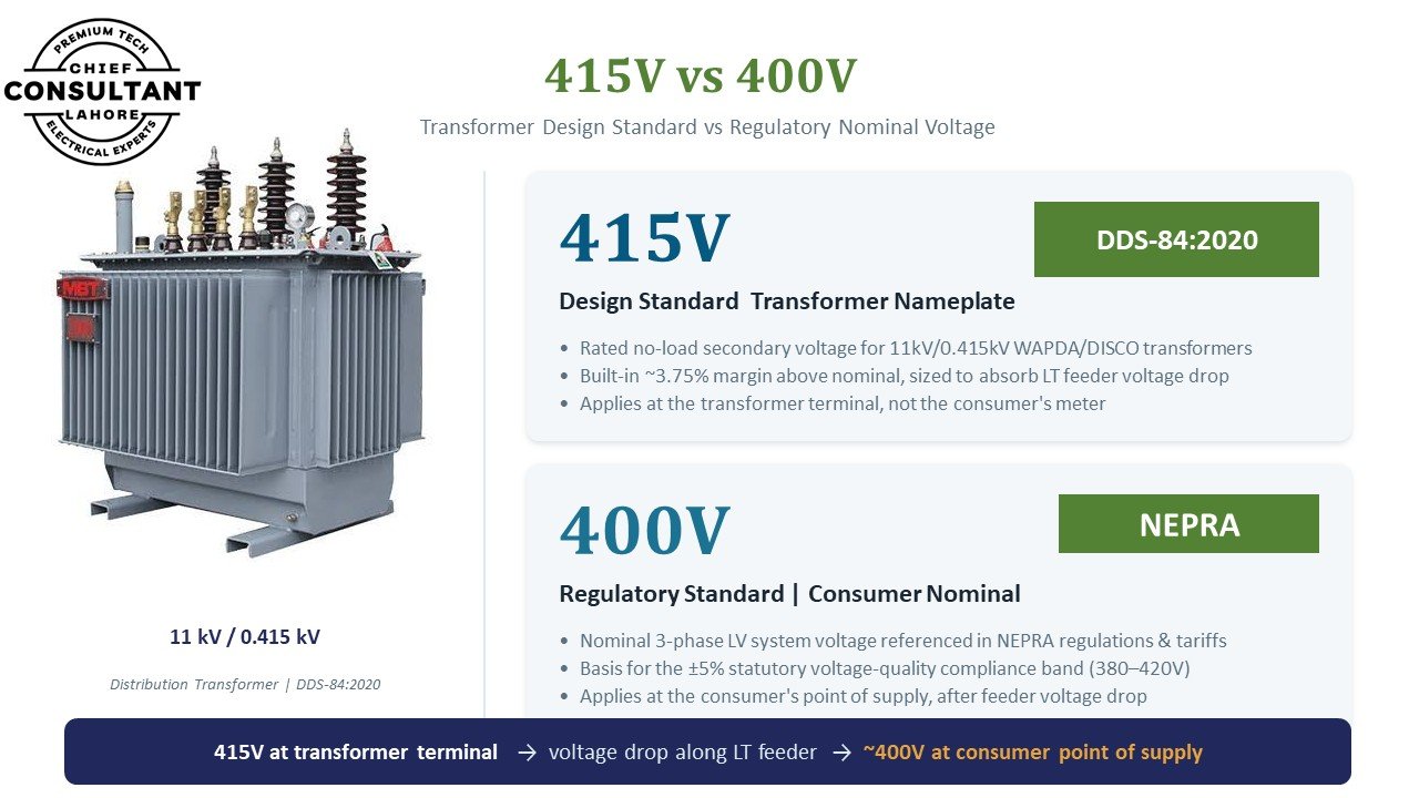
Why a Transformer Was Ever Designed at 415V in the First Place
When I was working in the field for a distribution company, the tap arrangement on our 11kV/0.415kV transformers followed a simple, deliberate logic. There were five taps. Tap 4 was the principal tap, the 415V design base. Tap 3 sat at plus 2.5 percent above that base. Tap 5 sat at minus 2.5 percent. Tap 2 sat at minus 5 percent, and tap 1 sat at minus 7.5 percent. Notice the shape of that arrangement. Four of the five taps exist to compensate for voltage falling below the base, and only one exists to compensate for voltage rising above it. That was not an oversight. It was a completely rational design for the world that transformer was built to serve. Our only real problem, at every distribution transformer I worked with in that era, was low voltage at the tail end of a long LT feeder. We designed the entire tap philosophy around tolerating that one direction of deviation, because bidirectional reverse power flow simply was not part of the operating reality we were solving for.
Every amendment that followed, right through to DDS-84:2020, kept refining the transformer around that same unspoken assumption. The engineering effort went into reducing transformer losses, improving core material, and tightening efficiency, all worthwhile work in its own right. But nobody sat down and asked the question that now matters most: what happens to this 415V design philosophy once a meaningful share of the load on that LV network can also generate?
Where the Numbers Actually Collide
Here is the part of this mismatch that I want every distribution engineer reading this to sit with carefully, because it is not an abstract regulatory quibble. It is a hard voltage arithmetic problem.
NEPRA’s OS-3 sets the upper voltage limit for LV consumers at 1.05 per unit, referenced against a 400V base. That works out to a ceiling of 420V. If a transformer is designed and nameplated at 415V, as DDS-84 specifies, the margin available to the downstream LV network before that 420V ceiling is breached is only 5V. Under reverse power flow, when rooftop solar generation on the LV side pushes voltage upward instead of the conventional load pulling it downward, that 5V margin is consumed extremely quickly, often long before the transformer’s own administrative loading cap would otherwise come into play. In practical terms, the transformer becomes voltage constrained in the reverse direction well before it becomes thermally constrained.
Now consider the alternative. If that same transformer’s LV side were instead designed and nameplated at 400V, matching NEPRA’s own operating standard rather than the historical 415V design base, the available margin to the 420V ceiling becomes 20V, four times larger. At that margin, the transformer can genuinely be loaded up to its full rated capacity in the reverse direction, absorbing DER export, without violating the 1.05 per unit upper limit that OS-3 itself sets. The transformer is not the problem in either scenario. The mismatch between which base voltage it was designed around and which base voltage the regulator uses to police voltage quality is the problem.
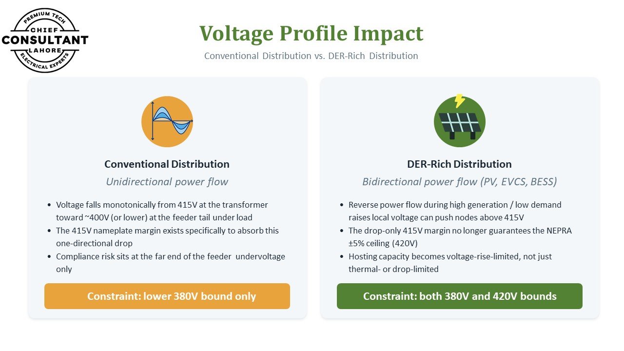
This is exactly what the second image illustrates. In conventional, unidirectional distribution, voltage falls monotonically from 415V at the transformer toward roughly 400V, or lower, at the feeder tail under load. The 415V nameplate margin exists specifically to absorb that one directional drop, and the only real compliance risk sits at the far end of the feeder, on the lower 380V bound. Once a feeder becomes DER rich, with meaningful photovoltaic generation, EV charging stations, and battery storage all capable of pushing power back onto the network during high generation and low demand periods, that same drop-only margin no longer guarantees staying under NEPRA’s upper 420V ceiling. Hosting capacity for DERs on that feeder becomes limited by voltage rise, not merely by thermal loading or by the old drop related concerns the standard was originally written to manage.
Why the Regulator Does Not See This
I say this without any personal grievance, only as an honest field observation after thirty three years of service: the biggest drawback in how this gap persists is that our regulator does not fully appreciate what is actually happening inside the standard it enforces, and how that standard plays out for a real consumer at the end of a real feeder. The practical reason for this is straightforward. Officers within the regulatory authority, by and large, do not carry the kind of field experience a DISCO or DNO field officer accumulates over years of walking feeders, climbing poles, and reading actual voltage complaints. Standards get written from a desk, based on what looks correct on paper, without the ground reality that a field officer lives with every single day. Closing that gap between paper and field has been, quite honestly, the work of my entire career.
There is a second, related gap on the transmission side. The S&S department, historically under WAPDA and now under NTDC, which I will refer to here by its current name, NGC, carries deep transmission line experience. That experience made complete sense when WAPDA operated as a single, vertically integrated utility, before 1998, when the system was one aggregated whole. But once WAPDA disintegrated into separate DISCOs, the standards that S&S continued to author remained transmission focused, written from the transmission side’s view of the problem. Nobody at that level was genuinely tasked with understanding, in detail, the distribution side’s actual field problems, including this exact 415V versus 400V question. The distribution planning function was left holding standards that were never really built with distribution’s evolving reality in mind.
What I Am Recommending
My recommendation is direct: we need an immediate DDS-84:2026 revision. Beyond whatever modernisation is done to transformer core material and efficiency, which is welcome and necessary work in its own right, this revision must correct the transformer’s base voltage to align with NEPRA’s own operating standard, rather than continuing to design around a historical 415V base that no longer reflects the network’s actual operating reality. Set the design base at 400V, in line with OS-3, and let the tap settings do the job they were always meant to do: absorb plus or minus 5 percent variation symmetrically, in both directions, rather than lopsidedly favouring protection against voltage drop alone.
| Design Base | Margin to 420V Ceiling | Reverse Power Hosting Capacity |
|---|---|---|
| 415V (current DDS-84 nameplate) | 5V | Voltage constrained well before thermal limit |
| 400V (aligned with NEPRA OS-3) | 20V | Can reach full rated capacity in reverse direction |
Three Messages, to Three Different Desks
I want this article to reach three specific audiences, because each one holds a different piece of this puzzle, and none of them can fix it alone.
Please leave the S&S department’s authority over distribution level standards to DISCO planning. Transmission expertise is real and valuable, but it is not the same expertise needed to correctly specify a distribution transformer that now has to survive bidirectional power flow on its LV side. Let the people who actually plan and operate the distribution network write the standards that govern it.
Please align your OS-3 operating standard with DDS design standards, or ask DDS to align with OS-3, but stop enforcing two standards that quietly assume two different base voltages for the same physical point in the network. A regulator that sets the 1.05 per unit ceiling has to understand what base voltage the transformer it is regulating was actually designed around, or the ceiling it sets will not mean what it thinks it means in the field.
Please wake up to where the network already is. DER penetration on many feeders has already crossed 20 percent of the connected kVA capacity of the feeder transformer. This is not a future planning scenario anymore. It is the operating condition on the ground today, and the voltage rise problem this article describes is already showing up in your feeders whether or not it has been formally recognised yet.
Key Takeaways
- 415V and 400V describe two different points on the same network, not two competing definitions. 415V is the transformer terminal design nameplate under DDS-84. 400V is the NEPRA OS-3 nominal reference at the consumer’s point of supply.
- The original tap philosophy was rational for its time. Four of five taps compensated for voltage drop because reverse power flow was not part of the operating reality in the 1990s and 2000s.
- The margin gap is a genuine engineering constraint, not a paperwork issue. A 415V design base leaves only 5V of headroom to the 420V ceiling; a 400V design base leaves 20V, four times the working margin for DER export.
- Hosting capacity is now voltage-rise-limited on DER rich feeders, a constraint the original standard was never written to address.
- This is a field level problem masked by a standards level gap between transmission-side authorship, regulatory desk work, and distribution-side ground reality, and closing it requires all three sides to actually talk to each other.
Why I Am Publishing This Publicly
I know this is not a problem unique to Pakistan. Engineers working in other parts of South Asia, in the Middle East, in Africa, and honestly even in some developed grids that adopted distributed generation faster than their standards could keep pace, are likely staring at some version of this exact same mismatch right now. A design standard written for one directional load flow, sitting alongside an operating standard that was never fully reconciled with it, quietly limiting how much distributed generation a network can actually host, long before anyone notices the standards themselves are the constraint. I am publishing this in the hope that it serves as a torch for anyone working on a DER impact study, wherever they happen to be sitting when they read it.